


Ensure the MagicDraw environment is set up for working on PLCSlib.
- The alias.properties file patched for working with PLCSlib located under
plcslib\etc\MagicDrawhas been copied to the data folder for your MagicDraw installation.NOTE This does require administrative permissions on Windows systems. - The path variable PLCSlib.data has been set to
plcslib\data. If not follow the procedure:- open MagicDraw
- goto
Options -> Environment - select
Path Variables - select
Add - set the name
PLCSlib.data - set the value to your local path to
plcslib\data - select
OK - select
OK
- MagicDraw has been set to save UUID's. If not follow the procedure:
- open MagicDraw
- goto
Options -> Environment - select
General - expand
Save/Load - set Save UUID to
true - select
OK
- Open Index Project
- Browse to
plcs\data\contexts\<<Context>> - Compare the date & time on the tool independent master index
index.xmiwith that on the MagicDraw specific indexdvlp\index.mdxml. If the tool independent master index is later than the MagicDraw specific index, or the MagicDraw specific index does not exist- Run the appropriate MagicDraw generation script on the tool independent index file.
Command:
plcslib\etc\Magicdraw\genMD.bat index.xmiNOTE On windows systems theThis will have created the MagicDraw index file based on the latest template specifications.index.xmifile can be dropped on the genMD batch file to execute.
- Run the appropriate MagicDraw generation script on the tool independent index file.
Command:
- Launch MagicDraw 17 and select
File -> Open Project... - Browse to
plcslib\data\contexts\<<Context>>\dvlp - Open
plcslib\data\contexts\<<Context>>\dvlp\index.mdxml
NOTE If you are warned that MagicDraw cannot find a number of modules then your MagicDraw Environment is not set up correctly. These are the XMI modules for the PLCS PSM and the templates. They are not found because the modules are referenced by relative paths using a path variable. Cancel the option to manually load each of the modules. SelectOptions-> EnvironmentSelectPathVariablesAdd a new path variable namedPLCSlib.dataand set the value to your localplcslib\datafolder Exit MagicDraw WITHOUT saving the project! - Browse to
- Add a new package for the template you are to create. The templates are organized
according to packages that reflect the context. Under Containment tab right click
on
Data/<<Context>>/Templatesand selectNew Element -> Package. Name the package<<Template>>. - Add a new SysML Block, named
<<Template>>and stereotyped as a Template, to the package named <<Template>>. (Right click on package just created in Containment tree and selectNew Element -> SysML Blocks -> Template). After adding the stereotyped block MagicDraw will immediately expect the name of the block to be entered. - Create a SysML Block Definition Diagram within your
<<Template>>package, named Template and place a block representing your template on the diagram.- Select your package in the Containment tree under
Data/<<Context>>/Templates/<<Package>>; - Right click and select
New Diagrams->SysML Diagrams->SysML Block Definition Diagram - Type "Template" as the SysML Block Definition Diagram name in Containment tree view;
- Drag the block icon for named
<<Template>>from the containment tree across to the diagram - Set the diagram size to
"Autosize"in order to reduce the size of the image.- Right click on diagram, select
"Diagram Properties" - size to
"Autosize"to"true"
- Right click on diagram, select
- Select your package in the Containment tree under
- Select the template package you have just created,
named <<Template>>, and execute
File->Export To->ModuleSelect "OK" in the resulting dialogue box. (If other dialogue boxes appear select "No".) In the resulting file chooser, browse toplcslib\data\contexts\<<Context>>\templates\<<Template>>\dvlp\and save the new template file as<<Context>><<Template>>.mdxml.NOTE The filetype should be changed to "MagicDraw File Types (.mdxml)" instead of the default .mdzip format. - Save, overwriting the
plcslib\data\contexts\<<Context>>\dvlp\index.mdxml - Close the project.
- Edit the project file
(
plcslib\data\contexts\<<Context>>\dvlp\index.mdxml) to replace the absolute module path to the newly created module with a relative module path using the path variable PLCSlib.data. i.e. replace as shown below:with<mdElement elementClass='FileProperty'> <value>D:\Users\CVSroot\plcslib\data\contexts\<<Context>>\templates\<<Template>>\dvlp</value> <selectionMode xmi:value='0'/> <displayFullPath xmi:value='true'/> <useFilePreviewer xmi:value='false'/> <displayAllFiles xmi:value='true'/> <fileType>FILE_TYPE_ANY</fileType> </mdElement><mdElement elementClass='FileProperty'> <value><PLCSlib.data>\contexts\<<Context>>\templates\<<Template>>\dvlp</value> <selectionMode xmi:value='0'/> <displayFullPath xmi:value='true'/> <useFilePreviewer xmi:value='false'/> <displayAllFiles xmi:value='true'/> <fileType>FILE_TYPE_ANY</fileType> </mdElement>NOTE This has been reported to and acknowledged by NoMagic as a BUG and should be fixed in later releases.NOTE Ensure that the editor used to perform this edit is a "dumb" editor and does not change the formatting of the file. Some editors have been found to alter the formatting resulting in the file becoming corrupted from a MagicDraw perspective.
- Reopen the project file
plcslib\data\contexts\<<Context>>\dvlp\index.mdxml - Export file as
<<Context>>\index.xml(overwriting the original).File -> Export To -> UML XMI 2.1 - Run the appropriate canonical XMI stripping scripts. Command:
plcslib\etc\Magicdraw\stripXMI.bat
                     <<Context>>\index.xml
- Open the template project that was previously exported in MagicDraw. templates\<<Template>>\dvlp\<<Context>><<Template>>.mdxml
-
When prompted by MagicDraw, agree to use the PLCS profile.
Select the module from the File system and
browse to
plcslib\data\contexts\dvlp\PLCS-profile.mdxml.
When you press finish you should be offered the opportunity to use Path variables.
Select the path variable form and press "Use Selected". - "Use" the PLCS PSM by selecting File->Use Module, selecting "From file system"
and browsing to
plcslib\data\PLCS\psm_model\dvlp\plcs_psm_module.mdxmlWhen you press finish you should be offered the opportunity to use Path variables. Select the path variable form and press "Use Selected".NOTE If you receive reports of the model being corrupted then you have probably not correctly installed the alias.properties file for MagicDraw. - If another template is being used in the definition of this template then "use" the
template as a module by selecting File->Use Module, selecting "From file system"
and browsing to:
plcslib\data\contexts\<<Context>>\templates\<<Template>>\dvlp\<<Context>><<Template>>.mdxmlWhen you press finish you should be offered the opportunity to use Path variables. Select the path variable form and press "Use Selected". - Identify the input parameters for your template.
These are either "Reference properties", "Part properties" or "Value properties".
- Reference properties - refer to objects that are not deletion dependent on the template. I.e. objects that may be used by / referenced by other templates. For example, Organization, Classification etc.
- Part properties - refer to objects that are deletion dependent on the template. These are principally Identifications and Descriptions. I.e. objects that are only instantiated/used in the context of the template
- Value properties - refer to simple types such as Strings, Booleans and Numbers.
-
Add constraints (named in camel case starting with upper case letter) to the block to handle Uniqueness requirements in the form OCL 2.0 as follows:
- Right click the Template block and select Specification;
- Select Constraints;
- Click "Create";
- Click the edit icon to the right of the unnamed constraint just created;
- Enter the name of the constraint;
NOTE The name shall be in camel case starting with upper case letter.
- Select "Specification";
- Click "...";
- Set the language to be OCL 2.0
- Enter the constraint body using:
- for a single unique property "propertyName":
<<Template>>::allInstances()->isUnique(<<propertyName>>)
- for a multiple unique properties "propertyName1", "propertyName2":
<<Template>>::allInstances()->isUnique(Sequence{<<propertyName1>>,
           			<<propertyName2>>})
- for a single unique property "propertyName":
- Click "OK";
- Click "Close"
- Arrange the layout of blocks to minimize the size of the image and the ensure that
the image shrinks to fit the layout.
- Right click on diagram, select "Diagram Properties"
- size to "Autosize" to "true"
- Save an image of the BDD in PNG format to <<Template>>\Template.png
-
Create a SysML Parametric Diagram for the <<Template>>.
- Select the template Block named <<Template>> in the Containment tree;
- right click and select New Diagram->SysML Diagrams->SysML Parametric Diagram
- On the "Select Parts" dialogue leave all properties selected;
- Click "OK"
An example of the resulting containment structure for the OASIS Requirement template is shown in Figure 1.
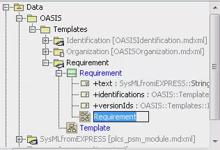 Figure 1 - SysML Parametric Diagram
 - Set the diagram size to "Autosize" in order to reduce the size of the image.
- Right click on diagram, select "Diagram Properties"
- size to "Autosize" to "true"
- Put all public properties on left side of diagram.
- Create the private properties as follows:
- Select a part or reference property from the diagram menu and drop it towards the right hand side of the frame;
- Select the type of the property from the "Select/Create Type for part" dialogue;
- Click "OK";
- Right click the new property and select Specification;
- Enter a name for the property;
- Ensure the visibility is set to Private;
- Enter the multiplicity for the property;
NOTE This signifies how many of these private properties will be created automatically when the template is instantiated.
- Click "Close".
- Right click the property and select Related Elements->Display Parts;
- Select those elements that are to be assigned to;
NOTE Ensure all properties with a lower multiplicity of 1 are shown since these are required.NOTE Sometimes the same property is shown more than once, this is because it is defined in both the supertype and then redefined in a subtype. Select the more specific type.
- Click "OK"
- If the private property is bound to a Template, then the property block should be coloured green. Right click and select Symbol(s) Properties. Set Fill colour to be Red: 204, Green: 255, Blue: 204
- Adjust the layout to minimize space.
- Build the structure of the private parts by using binding connectors to relate the
part values to the other private parts in the template.
NOTE Do not use a connector since this does not include the assignment semantics!
- Use binding connectors to link from the public properties to the properties within the private parts.
- Create the output ports as follows:
- Select a Flow port from the diagram menu and drop it on the right edge of the
frame;
NOTE The frame represents the Template itself so attaching the ports to the frame means assigning them to the template.
- Select the type of the port from the "Select Port Type" dialogue;
- Click "OK";
- Right click the new port and select Specification;
- Enter a name for the port;
- Set the flow direction as "Out";
- Ensure the visibility is set to Public;
- Enter the multiplicity for the property;
NOTE This signifies how many of these private properties can be accessed through the port.
- Click "Close".
- Adjust the layout to ensure the port labels are visible.
- Select a Flow port from the diagram menu and drop it on the right edge of the
frame;
- Use binding connectors to link from the ports to the objects being provided via that port.
- Show the flow ports on the Template Block diagram by right clicking on the template Block and selecting related Elements -> Display Ports
- Set up the default values for parameters of the template if appropriate
- Create an instance as defined below under "Create Instances for Template"
- Set the default value of the publicPart to be the instance
- on the public Part select "show default value"
- Save an image of the Para in PNG format to <<Template>>\<<Template>>.png
Instances are used for either default values inside the template or to reflect values expected by constraints.
- Create a package named "Instances" under
Data/<<Context>>/Templates/<<Template>> - Create a SysML Block Definition Diagram named "Instances" in the "Instances" package.
Select the "Instances" package that has just been created in the Containment tree,
i.e.
Data/<<Context>>/Templates/<<Template>>/Instancesright click and navigate the menu toDiagrams->SysML Diagrams->SysML Block Definition Diagramsand create a "SysML Block Definition Diagram". Name it "Instances" - Drag the Instance icon from the "Block definition" menu pane across to the diagram:
- Enter or select from the type to be instantiated.
- Right click on the instance and select "Specification"
- Enter the name of the instance.
- Click on "Slots" in the left hand frame
- For each property to be given a value:
- Select the property under the block in the centre frame
- Click "Create Value"
- Enter the value in the appropriate frame
- Click "Close"
- Save an image of the Instances diagram in PNG format to
<<Template>>\Instances.png
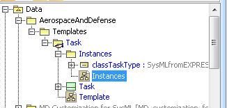
An example of the resulting package structure is shown in Figure 2. The Context is "AerospaceAndDefense" and the template is "Task".
Constraint may be defined for use within the template or to support the usage of the template within other templates.
- Create a package named "Constraints" tree under Data/<<Context>>/Templates/<<Template>>
- Select the constraints package in the Containment tree under Data/<<Context>>/Templates/<<Template>>/Constraints and go Diagrams->SysML Diagrams->SysML Block Definition Diagrams...
- Click "Add" in the resulting dialogue box.
- Type "Constraints" as the SysML Block Definition Diagram name in the "Create Diagram" dialogue which then appears
- Click "OK"
- Click "Close"
- Drag the Constraint Block icon from menu across to the diagram;
- Right click on the instance and select "Specification"
- Enter the name of the constraint.
- Click on "Parameters" in the left hand frame
- For each each input and output parameter Click "Create"
- Enter the name of the parameter;
- Enter the type of the parameter;
- Set the visibility of the parameter to Public;
- If the parameter is an output parameter then set isReadOnly to true;
NOTE This requires Properties: All to be set.
- Enter the multiplicity of the parameter;
- Click "Back";
- Click on "Constraints" in the left hand frame;
- Click "Create";
- Click the edit icon to the right of the unnamed constraint just created;
- Enter the name of the constraint;
NOTE The name shall be in camel case starting with upper case letter.
- Select "Specification";
- Click "...";
- Set the language to be OCL 2.0
- Enter the constraint body using:
<<outParam>>= - function of <<inParams>>
- Save an image of the Constraints diagram in PNG format to <<Template>>\<<Constraints>>.png
Assuming the Block or Template in the parameter diagram has a Classifier property which is the be extended in a new template using reference data, the procedure is as follows:
- Create an instance corresponding to each external class or NamedIndividual to be included
in the enumeration:
NOTE These may be created in the same template or in different templates.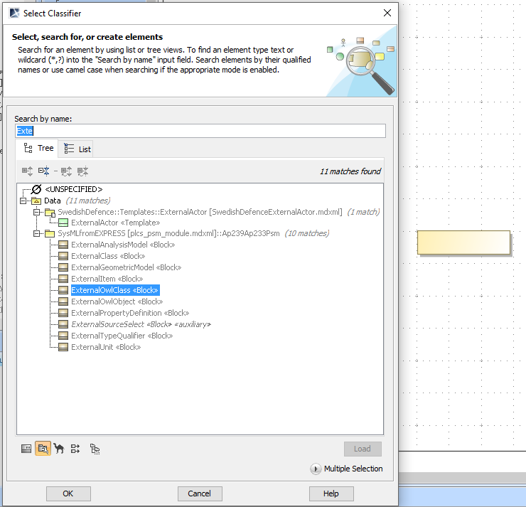 Figure 3 - An instance corresponding to an external OWL class.
 - Relate each instance to the relevant OWL class or NamedIndividual:
NOTE Open Instance specification > select Slots > select class > insert URL as Value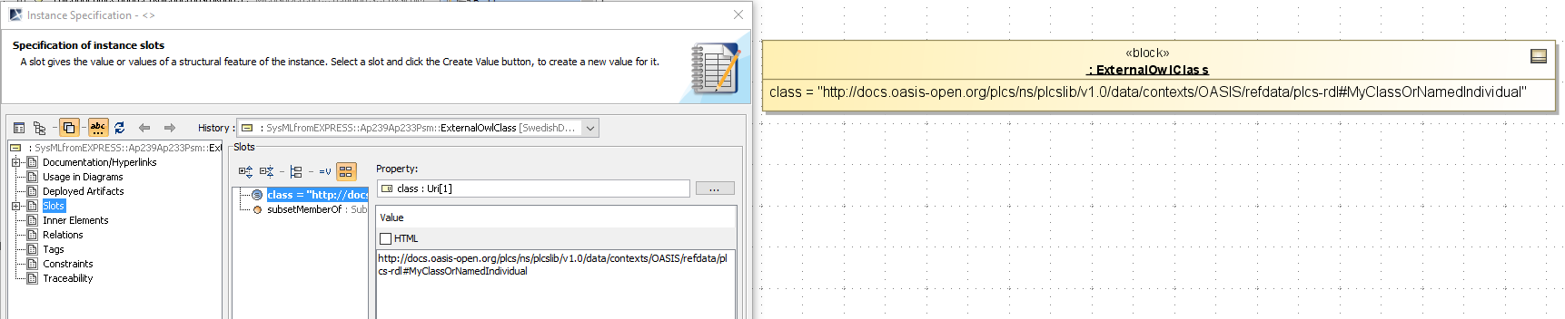 Figure 4 - An instance whose value references an OWL class.
 - Name the instance:
NOTE Open Instance specification > select Name > type (eg) "class<nameOfClass>"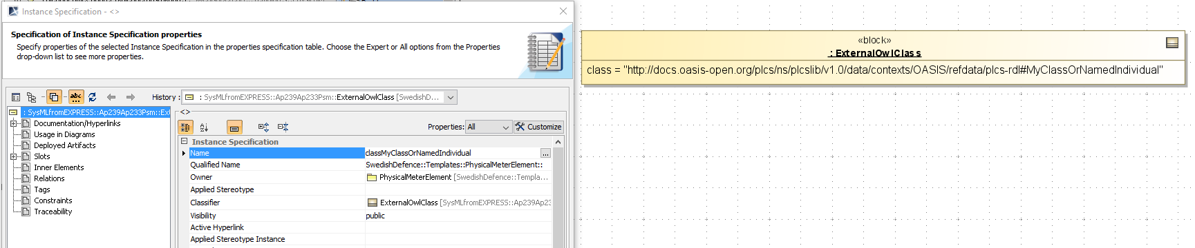 Figure 5 - Named instance.
 - Create an enumeration object on the Template diagram:
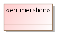 Figure 6 - Enumeration type
 - Apply the ValueType stereotype to the enumeration:
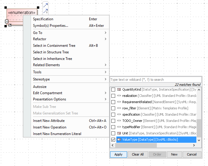 Figure 7 - Enumeration type with ValueType stereotype
 - Name the ValueType in accordance with the name of the new template property but using
an initial capital:
NOTE Thus, if the the template property will be named "myTemplateProperty", the ValueType should be named "MyTemplateProperty".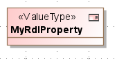 Figure 8 - ValueType with name
 - Add a property to the ValueType and name it "value":
NOTE Right click on the ValueType in the containment tree > New Element > property > type "value"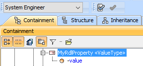 Figure 9 - Value property
 - Make value property public:
NOTE Open the value property in the diagram > Visibility > select "public"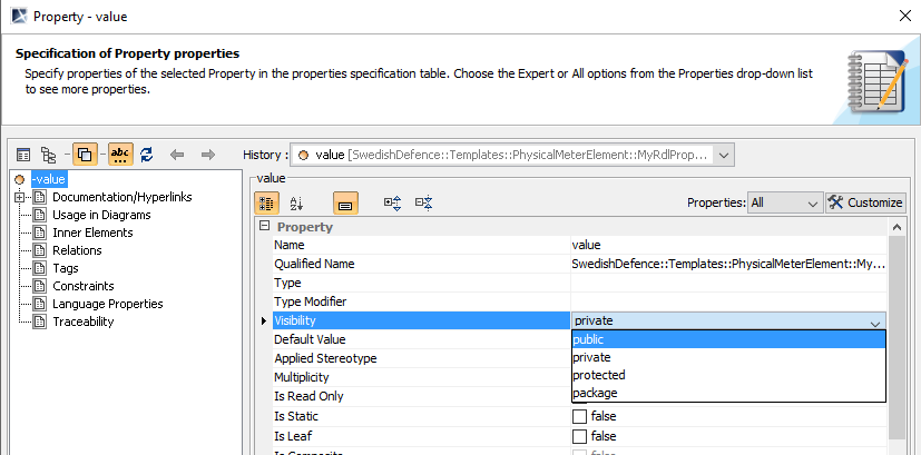 Figure 10 - Public value property
 - Set value property type to external class or NamedIndividual:
NOTE Open the value property in the diagram > Type > select ... > select ExternalOwlClass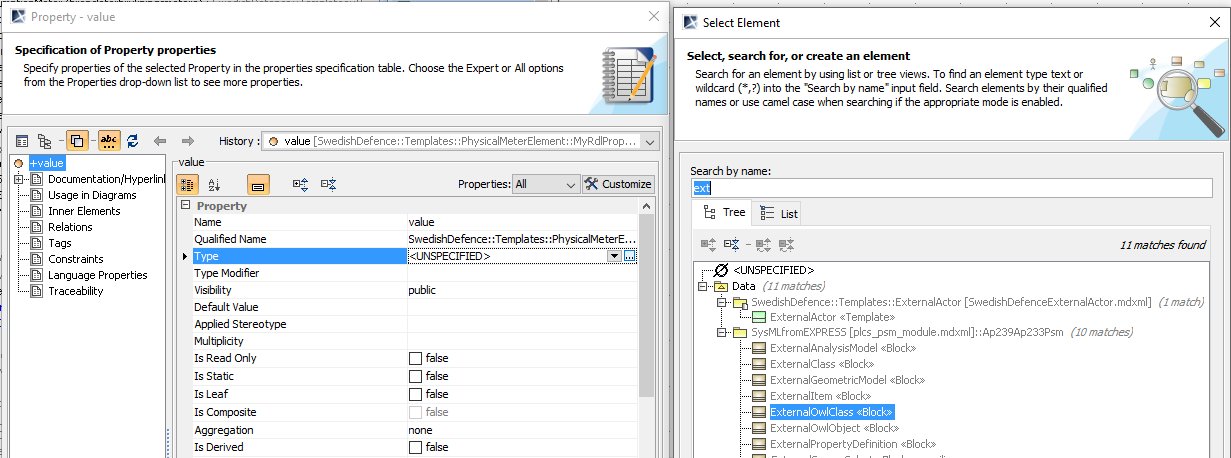 Figure 11 - Value property with type set to ExternalOwlClass
 - Create enumeration literals:
NOTE Right-click the ValueType in the diagram > Insert New Enumeration Literal > type name corresponding to the class or NamedIndividual to be used (the sting literal need not be the same as the name of the class or NamedIndividual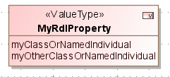 Figure 12 - Value property with two enumeration literals
 - Relate enumeration literals to RDL classes or NamedIndividuals:
NOTE Double-click each enumeration literal in the ValueType on the diagram > Slots > value > Create Value > select classe or NamedIndividual instance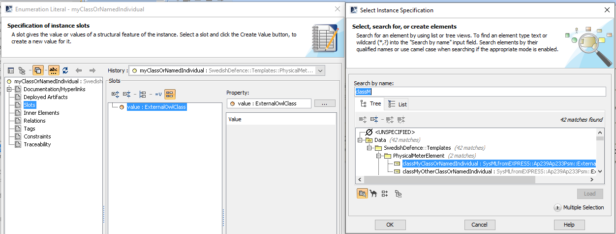 Figure 13 - Value related to RDL class instance
This should result in this sort of structure in the containment tree
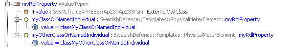 Figure 14 - Resulting containment tree
 - Create property in parametric diagram: 1 create classifier:
NOTE Drag a Part Property onto the parametric diagram > select Classifier template > create Name for classifer > set Multiplicity > right click and set Symbol Property > Fill Color > right click Related Elements > Display Parts > select class > join Classifier to Classifer property of the relevant Block or Template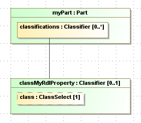 Figure 15 - Classifier bound to Classifier property of Template
 - Create property in parametric diagram: 2 create new property:
NOTE Drag a Value Property onto the parametric diagram > select ValueType created on Template diagram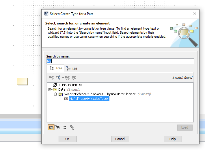 Figure 16 - Value Property bound to ValueType
 - Create property in parametric diagram: 3 name new property and make public:
NOTE Open Value Property > type name of property with initial lower-case letter > set Visibility to public > set Multiplicity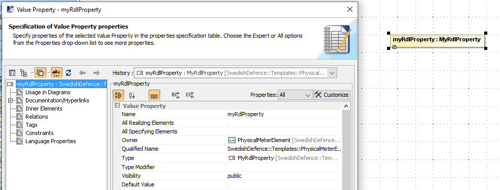 Figure 17 - Value Property named and made public
 - Create property in parametric diagram: 4 display Property for Value Property:
NOTE Right Click Value Property > Related Elements > Display Parts > select value > click OK Figure 18 - Value Property with displayed Property
 - Create property in parametric diagram: 5 Bind Property to ClassSelect of Classifier:
NOTE Place Value Property on left of parametric diagram and connect Property to ClassSelect using a Binding Connector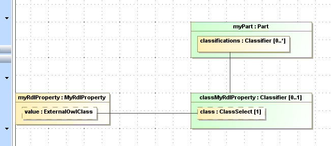 Figure 19 - Value Property bound to Classifier
 - Drag out value property in Template diagram:
NOTE Left click on value and drag out of Template area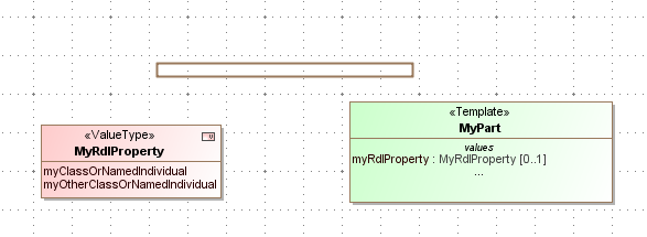 Figure 20 - Value Property dragged out
This will result in a the display of a connection between the Template object and the ValueType object like this:
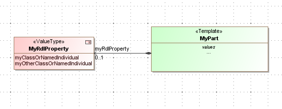 Figure 21 - Value property displayed as connected ValueType
- Export file as
<<Template>>\<<Template>>.xml
(overwriting the original).
File -> Export To -> UML XMI 2.1 - Run the appropriate canonical XMI stripping scripts. Command:
plcslib\etc\Magicdraw\stripXMI.bat <<Template>>\<<Template>>.xml - Run the Template XML Update Script to automatically populate the
Template attribute list . Command:
plcslib\etc\Ruby\updateTemplate.bat
                     <<Template>>\<<Template>>.xmi
